
 1 day ago
1
1 day ago
1
.jpeg)
Designed for engineers developing advanced communication, radar, and test systems, it offers a ready-to-implement blueprint for building high-performance RF receivers with reduced complexity and faster development cycles.
 Receiver
 As wireless communication, radar, and test instrumentation move toward higher bandwidths and direct-sampling architectures, engineers face increasing challenges in capturing wideband signals with precision and low distortion. This design addresses those needs by integrating a 4 GSPS ADC and an 8 GHz, DC-coupled differential amplifier, enabling direct conversion of RF signals without traditional frequency translation stages. Such capability simplifies system architecture, reduces latency, and enhances signal fidelity—key factors in modern applications like electronic warfare systems, software-defined radios, spectrum analyzers, and 5G/6G communication testers.
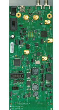
The TIDA-00431 reference design by Texas Instruments, presents a high-performance, wideband RF receiver architecture that integrates a 4 GSPS (gigasamples per second) analog-to-digital converter (ADC) with an 8 GHz, DC-coupled, fully differential amplifier front end. This configuration allows the system to capture signals starting from DC up to very high frequencies, making it ideal for broadband and multi-channel radio applications. Traditional designs using baluns cannot support true DC coupling; by contrast, this design’s amplifier front end grants direct coupling, preserving low‐frequency content while also enabling high frequency operation.
- Advertisement -

One of the key features of the design is its ability to support up to 2 GHz of instantaneous RF bandwidth, allowing wide instantaneous coverage of the spectrum. It handles both single-ended and differential inputs, providing flexibility to interface with different types of RF sources. In addition to the signal chain, the reference design includes a complete clocking solution and a full power management scheme, so that designers need not reinvent key support circuits. The system is targeted toward demanding applications like defense radios, vector signal transceivers, and wireless communications testing.
While a fully assembled evaluation board has been built and characterized for performance verification, it is not offered for sale. Instead, the project includes design artifacts to facilitate adoption: a design guide detailing architecture and performance data; an assembly drawing for component placement; a bill of materials listing designators and part numbers; CAD/CAE files for mechanical integration; Gerber files for PCB fabrication; a layout plot of the PCB layers; and a full schematic capturing the interconnections. These deliverables streamline the path from concept to prototyping.
TI components form the backbone of the TIDA-00431 design, ensuring precision, low noise, and high-speed performance. The power architecture uses ultra-low dropout regulators such as LP38513-ADJ, TPS79301-EP, TPS723-Q1, and LP3878-ADJ for clean, stable supply rails. For clock generation, the LMK04828 provides jitter cleaning and JESD204B compliance, while the TRF3765 serves as a low-noise PLL/synthesizer from 300 MHz to 4.8 GHz. The LMH5401 differential amplifier drives the ADC12J4000, a 12-bit, 4 GSPS converter that captures wideband RF signals directly. Supporting elements like the LMR70503 and LM26400Y manage power efficiently, while SN74AVC4T774, LMC6762, SN74LVC1G125, and LM95233 handle logic, control, and temperature monitoring.
For design engineers, the TIDA-00431 provides not only a proven hardware blueprint but also comprehensive documentation, layout guidance, and power management strategies that shorten development cycles and minimize design risks in building next-generation high-performance RF receivers.TI has tested this reference design. It comes with a bill of materials (BOM), schematics, assembly drawing, printed circuit board (PCB) layout, and more. The company’s website has additional data about the reference design. To read more about this reference design, click here.


.jpeg)


 English (US) ·